A machine having some interesting features is the Strela (Arrow). This was a machine with a Williams tube memory of 2,048 words of 43 bits. The first Strela went into operation in 1953, but additions and improvements were made to the machine during its lifetime.
The machine's ordinary arithmetic instructions performed floating-point arithmetic only, but it also had address arithmetic instructions to perform addition or subtraction on the three address fields of an instruction in parallel.
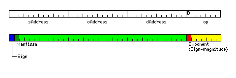
Addresses were 12 bits long; the second half of the address space was used for I/O and for a number of constants.
The instruction format and floating-point format of the machine are shown below:
This site gives a description of the instruction set of this computer; most of the instructions are also described in the famous book Computer Structures: Readings and Examples by Bell and Newell.
The B bit in an instruction is used to set a breakpoint at the instruction. The computer would halt at instructions so flagged if a console switch enabled this.
The basic instructions were:
000001 Add
000010 Add the three address fields of [operand] to the three address
       fields of [source] in parallel, storing the result (with the
       original opcode and break fields of [source]) in [destination]
000011 Subtract
000100 store abs([source]) - abs([operand]) in [destination]
000101 Multiply
000110 Add exponent field of [operand] to exponent field of [source],
       storing the result (with the original mantissa field of [source])
       in [destination]
000111 Subtract exponent field of [operand] from [source]
       (result in [destination] as above)
001000 Replace the sign of [source] with that of [operand], storing the
       result in [destination]
001001 AND
001010 Add without rounding
001011 OR
001100 Shift the mantissa field of [source] the number of bits
       indicated by the exponent field of [operand], storing the
       result in [destination]
001101 Subtract the three address fields of [operand] from the three
       address fields of [source] in parallel, storing the result in
       [destination] as above
001110 XOR
001111 One's complement 43-bit integer addition
010000 Conditional jump; branch to either [source] or [operand]
010110 XOR and halt if result not zero
010111 Conditional jump to subroutine; branch to either [source] or [operand] and
       store return address at [destination] in the form of a conditional jump
Conditional jumps were based on a test flag that was set if the result of addition or subtraction was negative, if the result of multiplication was greater than or equal to 1 in absolute value, if the result of AND or OR was zero, and if the result of XOR was nonzero.
There was also a shift instruction that used the immediate value in the operand field to indicate the number of shifts, but its opcode is not available in my references.
A series of prefix instructions existed, with opcodes of the form 011sod. The operand field indicates how many times the following instruction will be repeated, and if the destination field contains a nonzero address, that location will be cleared before the repetition. The bits s, o, and d indicated which, if any, of the address fields of that instruction would be incremented (not changing the actual instruction stored in the next location) with each iteration. The Univac 1103, a two-address computer, had a similar repeat instruction.
There were several built-in subroutines that could be invoked by single instructions. They generally calculated functions of the source argument to store in the destination argument. The repeat prefixes, of course, could not be used in them, but the operand field of the instruction calling the subroutine was used to indicate the number of successive locations on which to perform the function. Thus, the sine instruction, if it had 0 in its operand field, calculated the sine of the number in [source], storing it in [destination], but if it had 10 in its operand field, it calculated the sines of 11 successive values, starting with the one at the source address, and stored them in 11 successive locations, starting at the destination address.
These subroutines were:
110000 block move
110010 reciprocal
110011 square root
110100 exponential
110110 logarithm
110111 sine
111000 binary to decimal
111010 decimal to binary
111011 arctangent
111100 arcsine
Conversions between decimal and binary converted to and from a decimal form in which the mantissa field, expanded by one bit, contained BCD digits and the exponent field, shrunk by one bit, contained a base-10 exponent in binary form. The block move subroutine used one's complement addition of the whole 43 bits to calculate a checksum: on some Strelas, the checksum was placed at the destination address, and the data to be moved after it, and on others, the data to be moved ended up starting at that address, and the checksum came after the block.
Another interesting feature the Strela had was that its magnetic tape was divided into zones in which up to 2,048 numbers could be written; the tape could be advanced to any zone, and writing data into that zone did not affect what came after it on the tape. Thus, like DECtape and LINCtape, it used magnetic tape to perform the kind of function we normally associate with disks.
Although the Strela was not a pipelined computer, that sort of thing coming later with such computers as the BESM-6 in the Soviet Union, and the STRETCH, the 7094, the 360/91, or the Control Data 6600 in the United States, it certainly is interesting that it was designed so that were an attempt to be made to write a compiler to generate code for it, that compiler would have to generate vectorized code to use it effectively. Doing so, though, was beyond the state of the art during that computer's lifetime.