This section describes the format of the operand of a Define Extended Translate instruction when its code field is equal to zero.
In order to understand the format of these programs, some basic concepts will have to be understood.
The first 16 bits of a program is a halfword containing an unsigned integer indicating how many 16 bit words follow to constitute the program.
A program is a series of cycles. A cycle contains the following operations:
Not all of these steps need take place in any cycle.
The fetch, store, and translate operations involve references to memory, and they are slower than calculation steps. Thus, the results of the fetch and the translate are present at the end of the cycle, and the value used by the store and as the index by the translate must be provided at the beginning of the cycle.
The degree to which these operations are slower than calculations depends on the implementation, and so the number of calculation steps allowed per cycle is not limited; a cycle can contain only one calculation step, or any number permitted by the maximum length of a program. But this should make clear the intended result of the DET instruction: the code for the calculation steps is to be loaded into internal memory which is considerably faster than normal memory, ideally, into register space, not merely cache memory. Whether or not this happens is intended to be determined by the length of the definition of a translate instruction, so that the architecture, which defines the possible instructions, is not constrained by the characteristics of a specific implementation.
Naturally, to do something useful, one wishes to first perform a fetch, then perform a calculation on its result, and then store the result of that calculation. How is this reconciled with the structure of a cycle as outlined above?
A cycle begins with a series of fields which indicates the pipelining order of each of the elements of the cycle. How this works is indicated below:
(Incidentally, to give credit where it is due, I believe that the layout of this diagram may have been inspired by a vague memory of something I saw in documentation for the Packard-Bell 440 computer.)
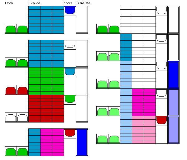
In the column at the left of the diagram above, three example instruction programs are illustrated.
The first example is a program that does a fetch, followed by a calculate, and a store.
The fetch operations are shown in green. This indicates they are performed the first time the cycle is executed. Both are shown in green, so a byte is fetched from both the source operand and from the aux source operand.
The calculate operations are shown in blue-green. They work on the result of the fetch operation performed in the preceding cycle. So they begin to be performed only the second time the cycle is executed. The calculation might be, for example, to choose the lesser of the two bytes fetched, and to set a flag so that the byte not chosen is not fetched again on the next cycle; this would merge two strings with sorted bytes. Of course, as the source strings eventually end, that task would require some additional complications.
The store operation is shown in blue. This operation stores the result of the calculate operation performed in the preceding cycle. So this operation only begins to be performed the third time the cycle is executed.
Then, the next part of the illustration shows parts of three successive iterations of this program, with the same color applied to each part of an iteration, to show that for any one iteration, the fetch comes first, then the execute, and finally the store.
The second example is a program that does a fetch, followed by some calculations, followed by a translate, followed by more calculations, followed by a store.
It is shown as composed of three cycles, which are performed one after the other in a loop.
On the first pass through the three cycles, the operations shown in green are performed: first the fetch, then the first group of calculations, then the translate.
On the second pass through the three cycles, although the operations shown in green are also performed, on the next pair of bytes that are fetched, the first set of bytes continues to be processed using the operations shown in blue, which are now performed for the first time: first, a second set of calculations, then a store.
The third example shows another way of handling this type of situation. Here, the three parallel calculation sequences are allocated to two different levels in the pipeline.
Thus, only the fetch operations, shown in green, are performed the first time this single cycle is executed.
The first column of calculation operations, shown in blue-green, begin to be performed the second time.
The translation operation, shown in blue, begins to be performed the third time.
The second and third columns of calculation operations are shown in purple, and are started the fourth time the cycle is executed.
The store operation is shown in red, and begins to be performed the fifth time the cycle is executed.
Note that, although in the examples, the fetch operations are begun first, and the store operation is begun last, this is not necessarily true of every cycle.
The column at the right shows several iterations of the cycle of the third example. A lighter color is used to indicate subsequent operations which handle later pairs of characters being processed.
What happens when the strings being processed come to an end?
There are two basic cases to be considered.
In one case, something is encountered that indicates that processing may cease at once. In that case, processing of steps associated with the pipeline level at which this decision is made stops, but steps associated with earlier characters continue to be executed.
In the other case, something is encountered that indicates that processing the current item should continue, but processing of any additional characters should not be initiated. Here, the upper limit to the pipeline level allowed is one place higher; again, it decreases by one per pass.
The diagram below shows the format of the program code for an instruction.
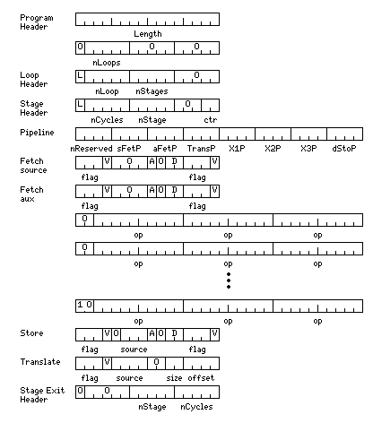
A program begins with a 32-bit header. Its first halfword, as noted above, is an indication of the total length of the program in halfwords. The next halfword of the header indicates the number of loops in the program, which can be up to 31. The first bit, and the last ten bits, of that halfword of the header are not used and must be zero.
Each loop begins with a one-halfword loop header. The first bit in that header, labelled L, is zero except for the last loop in the program, in which it is one. The next field gives the number of the loop, from 1 to 31. Then, another five-bit field gives the number of stages in the loop. The last five bits of the header are not used, and must be zero.
Each stage begins with a one-halfword stage header. The first bit in that header, labelled L, is zero except for the last stage in a loop, in which it is one. The next field gives the number of cycles within this stage which precede the next stage. Then, the next field gives the number of the current stage, from 1 to 31. After three unused bits, which must be zero, a two-bit field indicates the source for the initial value of the counter of this stage. This source has four possible values:
00 The length field of the Execute Extended Translate instruction
01 The initial value of the counter of the next outer stage
10 The current value of the counter of the next outer stage
11 The number 1
Each loop in the program is actually a series of nested loops, and each one of these loops is what is called a stage. The counter is the number of times the stage will be executed. Following the way in which the original HARVEST computer worked, it is intended that the next outer loop can modify the counter in its stage exit portion, incrementing or decrementing it. This allows instructions to operate on matrices represented in diagonal form: one stage can execute for the number of times in the length field of the Execute Extended Translate instruction, and then the next inner stage can either have a counter that starts with the value of the length field, and is being decremented, or a counter that starts with the value of 1 and is being incremented.
Note that the item called a counter gives the number of times the loop is executed, so it is only the source for a value that is copied into an actual counter which could be thought of as being decremented for each iteration.
After these three headers, the diagram shows a single cycle, with a one-halfword stage exit header following it.
The stage exit header always begins with a first bit of zero and a five-bit all-zero field. It then continues with five bits giving the number of the current stage, and five bits giving the number of cycles belonging to the current stage which follow the stage exit header, which itself follows the next inner stage. Thus, each stage that has a next inner stage with it in the same loop is divided into two segments, an entry segment that preceeds the next inner stage and an exit segment which follows it.
The format of a cycle is as follows:
The first two halfwords of the cycle description give the pipeline stage associated with the various operations that may take place in the cycle.
These operations are the source fetch, the aux source fetch, the translate, the three execution sequences, and the destination store.
The first item, nReserved, contains the number of additional alternate execution sequences included in the cycle description. This permits a limited form of conditional branching without disrupting the sequence of pipelined operations.
The pipeline stage number, if zero, indicates the operation does not occur during the current cycle. For the fetch, store, and translate operations, a zero value indicates the halfword describing the operation is omitted from the cycle description. Only if all three execution sequences have a zero value will the section of operation codes be omitted.
The pipeline stage number can be a value from 1 to 7. A segment of the cycle having a pipeline stage number of 1 is executed the first time the current loop is performed; one having a pipeline stage number of 2 is executed for the first time the second time the loop is performed, and so on.
The words for a fetch operation have the same format for both the fetch from the source operand and the fetch from the aux source operand.
The first field is either 0, indicating that the fetch is performed unconditionally, or 1 to 7, indicating the fetch is performed if flag 1 to 7 has the value indicated by the following V field.
All 7 flags initially have the value 0 on entering an instruction, so that this test can be used, without additional setup, either for a fetch that is to be performed unless disabled, or a fetch that is to be performed only when enabled, in the first cycle in the first loop of an instruction.
The A bit indicates whether the pointer for the respective operand is to be advanced after the operation.
The D field has the following values:
00: do not decrement the counter

10: set flag if counter zero, then decrement counter
11: decrement counter, then set flag if counter zero
and the subsequent flag and V fields indicate which flag to set, and the value to which to set the flag.
The store instruction also begins with a flag and V field to determine the conditions under which the store takes place. As well, it contains a source field to determine what value is stored. The values of this field are:
000: result from last Fetch Source operation
001: result from last Fetch Aux Source operation
010: accumulator of first execution thread at end of previous cycle
011: accumulator of second execution thread at end of previous cycle
100: accumulator of third execution thread at end of previous cycle
101: last value stored by a Store operation
110: result from last Translate operation
111: secondary item result from last Translate operation
For values 010, 011, and 100, the accumulator which is referenced is the accumulator having the type of the instruction, since the instruction type determines the kind of values that are read and stored.
The store portion of a cycle has three possible formats, only one of which could be shown in a diagram of the entire cycle of the form above. The three formats are:
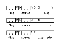
In the format shown in the first line. the instruction contains a D field, a second flag field, and a second V bit, in the same manner as the fetch words.
In the format shown in the second line, the A bit is not used, and the displacement field shown is used instead. The displacement field has the same interpretation as a source field, and indicates the source of a value which indicates how many positions before the current destination pointer the value to be stored will be placed.
In the format shown in the third line, storage is done to the translate table instead of the source string. For some operations, an area at the end of the translate table can be used to contain a set of counters to collect statistics about the source and aux source strings or the relationship between them. The T bit, if 0, indicates an item of the type specified in the instruction opcode is stored; if 1, that a 16-bit halfword is stored. It also modifies the interpretation of the source field of the instruction, treated as if it precedes that field to create the four-bit source field used in the translate instruction.
The disp and ptr fields always refer to 16-bit accumulators, but they can be zero to indicate they are not used. The sum of the values in them is used to point into the translate table to the place where the selected value is stored.
The translate instruction has a size field indicating the size of the entries in the translate table:
00: one item
01: two items
10: two items and one pointer
If one item, the item found in the table is placed in source position 6 for future instructions.
If two items, the first item found in the table entry referenced is placed in source position 6 for future instructions, and the second item there is placed in source position 7.
If four bytes, the first and second items are placed as above, and the pointer is placed in source position 14.
The source field, if its value begins with a zero bit, has almost the same interpretation as in the store instruction, except that when referring to an execution thread, it always refers, no matter what the type of the instruction, to the byte accumulator of the thread referenced. When the type of the instruction is other than byte or halfword, it can only refer to the execution threads; but since a 16-bit value is acceptable as a translation pointer, such values can be accepted from the fetch, store, and translate areas as well.
The other possible values are:
1010: first execution thread halfword accumulator
1011: second execution thread halfword accumulator
1100: third execution thread halfword accumulator

1110: pointer value from last Translate operation
Since there are multiple execution threads, each type of operation can save values only in its own registers, but can read the registers of other threads, to eliminate the need to arbitrate conflicts.
Between the fetch and store words, the execute operations are defined.
If nReserved is zero, the format of this area is simple: a sequence of words, containing the opcodes of the operations in execution units 1, 2, and 3 in parallel, terminated by a word beginning with 10 instead of 00.
When nReserved is not zero, each of these words, except the first, is followed by one or more words with the opcodes for the reserved threads. The terminating 10 bit pair occurs in the first word, that containing the opcodes for the original three threads, of the series of opcodes for the last execution step of the cycle.
If a word begins with either 01 or 11, it is currently envisaged that this will indicate that instead of containing three 10-bit opcodes, the word contains a single 30-bit instruction code, to be performed unconditionally in that execution step. The next word begins the description of the next execution step if 01 begins the word; no reserved thread opcodes are associated with the word.
The possible opcodes are:
00000 00000 NOP No operation
00000 00001 SWH Swap halves of the accumulator
00000 00010 INC Increment accumulator
00000 00011 INV Invert all the bits of the accumulator
00000 00100 ASP Add accumulator contents to source pointer
00000 00101 ADP Add accumulator contents to destination pointer
00000 00110 GCC Load accumulator with current counter for next inner stage
                (valid only in exit segment of current stage)
00000 00111 GIC Load accumulator with initial counter for next inner stage
                (valid only in exit segment of current stage)

00000 01aaa RTV Load accumulator from source field aaa of same length

00000 10nnn SCT Set current type

00001 00aaa HLD If flag aaa is set, iterate current cycle instead of
                proceeding with loop
00001 01aaa REL If flag aaa is set, clear iteration of current cycle,
                and fall through and continue with loop
00001 11100 IIS Increment counter of next inner stage
                (valid only in exit segment of current stage)
00001 11101 DIS Decrement counter of next inner stage
                (valid only in exit segment of current stage)
00001 11110 CON On next loop iteration, ignore operations at
                pipeline level 1, and increase the lower limit by
                1 with each loop until execution ceases.
00001 11111 Q   In current loop, stop executing this thread,
                in any later cycles within this loop, do not
                execute operations at the pipeline level of this
                thread, and in subsequent loop iterations, do not
                execute operations at the pipeline level of this
                thread plus 1 for each iteration, and in addition
                set a lower limit as in the CON instruction.

00010 00aaa SFP Set flag aaa if accumulator contents are positive
00010 01aaa SFZ Set flag aaa if accumulator contents are zero
00010 10aaa SFN Set flag aaa if accumulator contents are negative

00011 00aaa CF  Clear flag aaa
00011 01aaa SF  Set flag aaa
00011 10aaa XC  Execute following instructions only if flag aaa is clear
00011 11aaa XS  Execute following instructions only if flag aaa is set

00100 iiiii II  Enter value iiiii in accumulator
00101 nnnnn CYC At end of cycle, branch to cycle nnnnn of current
                stage segment
00110 nnnnn LF  Perform CON, then proceed to loop nnnnn
00111 nnnnn LP  At end of cycle, branch to initial cycle of loop nnnnn

01aaa nnnnn STC Switch to executing opcodes from thread nnnnn if flag aaa is 1

10010 nnnnn L   Recall the value in scratchpad nnn
10011 nnnnn ST  Store current accumulator in scratchpad nnn
10100 nnnnn A   Add contents of scratchpad nnn to accumulator
10101 nnnnn S   Subtract contents of scratchpad nnn from accumulator
10110 nnnnn M   Multiply accumulator by contents of scratchpad nnn
10111 nnnnn D   Divide accumulator by contents of scratchpad nnn

11000 nnnnn N   AND contents of scratchpad nnn with accumulator
11001 nnnnn O   OR contents of scratchpad nnn with accumulator
11010 nnnnn X   XOR contents of scratchpad nnn with accumulator
Each of the three active instruction threads has its own set of eight sets of 32 scratchpad registers, one set for each of the eight standard scalar data types, and eight accumulators, again, one for each of the standard scalar data types, between which it can switch. The accumulators and scratchpad registers are associated with the execution units, so an STC instruction changes the code used, not the registers used, in any of the three active threads.
The XC and XS instructions cause following instructions to be ignored only until the end of the current cycle, or until the next XC or XS instruction, and so they cannot be nested. The XC 0 instruction, as there is no flag 0, is used to unconditionally resume executing instructions in the current thread.
The STC instruction is ignored if these instructions cause following instructions to be ignored, so the XC and XS instructions can be nested across threads although they cannot be nested within a thread.
Note that to support the Q instruction properly, a shift register must be used to indicate which pipeline levels are to be executed in any given loop iteration. As well, individual executions need to be flagged, and there need to be certain registers checked at the end of any cycle.
It is important to note that it is the programmer's responsibility, through reading values with the RTV instruction, or through choosing the appropriate values for the source fields of the translate and store halfwords in a cycle, to ensure that portions of the cycle activated in successive pipeline stages are actually engaged in processing information originating from the same fetch operation.
The CYC, LF, and LP instructions, which allow true conditional branching, are needed in order to handle such things as the use of multiple translate table references for table-driven instructions. The CYC and LP instructions preserve the current pipeline status, while the LF instruction allows the current pipeline to wind down normally, and the new one to start again with the items at pipeline level 1. It is intended that the LP instruction is to be used with loops either including duplicate code where needed to match unchanged portions of the operation, or simply leaving untouched resources used by the pipeline stages to be resumed later.
The HLD and REL instructions provide an alternative and simpler means, particularly when combined with the STC instruction, of handling the case when a translate operation might result in a variable number of table references.
Also note that the format of programs in memory is such that they include areas shown as 32-bit words that may be aligned only on 16-bit boundaries. This should not be taken as a concern, as the DTP instruction is to be viewed as copying the program it points to from memory to another area of the machine suitable to high-speed execution of the procedure.