Some of the possible combinations of scales on a slide rule have received standardized names. In 1859, Amédée Mannheim developed a slide rule with the scale layout
A/B C/D
(this standardized notation means that the scales are A on the top of the body, B and C on the slider, and D on the bottom of the slider) with a cursor. In some senses, this could be thought of as the first modern slide rule, and Mannheim's design was the occasion for a great increase in the use and popularity of the slide rule.
Shortly after Mannheim's design of the slide rule, another design was also introduced, the "Règle des Ecoles", which had the scale layout
DF/CF C/D
in modern terms, although the scales were actually still labelled A, B, C, and D in order. This arrangement survived on the reverse of many elaborate duplex slide rules, with accompanying CIF and CI scales, to allow more efficient multiplication.
During much of the 20th century, a slide rule advertised as a Mannheim would (thankfully) have a somewhat more elaborate layout:
A/B CI C/D K
S L T
where the S, L, and T scales were on the reverse of the slide, and the S scale usually was made to coincide with the A scale. Keuffel and Esser, on the other hand, used their trademark "Polyphase" to refer to this type of rule, and used the term "Mannheim" for one without the CI and K scales, but still with the S, L, and T scales on the back of the slider.
In Europe, the term "Rietz" was often used for slide rules which had a few more scales than the original Mannheim rule; a common scale layout to which this term was applied was:
K A/B CI C/D L
S ST T
Here, the presence of the ST scale shows that the S scale works with the C and D scales through the use of the cursor. Many slide rules with this complement of scales, but in different arrangements, were made for use in Europe.The original Rietz slide rule, however, did not include an ST scale.
The term "Darmstadt" or "Système Darmstadt" refers to a simplex rule with log-log scales, having an arrangement such as:
S T A/B K CI C/D P
L LL1 LL2 LL3
and, again, there were many variations on this scale arrangement, most of them minor. Unlike the Rietz slide rule, there was a large enough difference between this and the type usually sold as a Mannheim slide rule for it to also establish a foothold in the North American market, especially during the early years when Keuffel & Esser held patents on the duplex log-log slide rule.
The Darmstadt arrangment of slide rule, however, is a relatively recent one, which originated only in 1934, long after both the Yokota slide rule from 1907 and the duplex log-log slide rule (the first example of which, the K&E 4092, apparently dates from 1909 or earlier): this surprised me when I heard it, as I would have expected that some form of simplex slide rule with only one set of log-log scales would have been in use, likely for a long time, before either the Yokota or the duplex log-log slide rules were developed.
Of course, it could well have been that such slide rules did precede the Yokota and the duplex log-log, just without being developed to a standardized type like the Darmstadt.
Both Mannheim and Darmstadt slide rules usually had, on the back, two small windows with hairlines corresponding to the two index positions on the stator. This allowed the use of the scales on the back of the slider without turning the slider over.
In the case of the Mannheim, bringing an angle on the S or T scale to the appropriate one of the hairlines would allow a number on the body of the rule to be multiplied by a sine or tangent, and then found on the slider.
In the case of the Darmstadt, taking a number to a power without reversing the slider is more complicated, but it can be done. Put the number to be raised to a power on one of the hairlines, then, on the front of the rule, place the cursor where the index of the slider is located. Although this position reflects the inverse of that number's position on the log-log scale, one still moves the power on the C scale of the slider to the cursor (and not the CI scale) in order to advance the log-log scale so that the number raised to that power will appear at one of the index hairlines on the back.
The Darmstadt slide rule, with log-log scales and trig scales, offered all the standard mathematical functions commonly found on general-purpose slide rules. However, placing the trigonometric scales on the body of the rule meant that products involving more than one trigonometric function would require writing down intermediate results; because of how the log-log scales are usually used, no benefit is derived from placing them on the slider.
Thus, the scale layout on the Yokota slide rule, a simplex or closed construction slide rule patented in 1907:
LL3 LL2 LL1 A/B K C/D LL01 LL02 LL03
S Sec T
although it lacks a CI scale, would seem to me to have been an even better basis on which to arrange a slide rule than the Darmstadt design, but although duplex designs did proceed in that direction, simplex designs generally did not.
The secant being the reciprocal of the cosine, the secant scale served as an SI or inverse sine scale, except that one would subtract the angle from 90 in one's head, so the effort is split evenly between sines and cosines.
The original Yokota slide rule differed from modern slide rules with log-log scales in aligning them so that 3.5, rather than e (2.71828), on the LL3 scale corresponded with the index. As with those Pickett log-log slide rules that use base 10, this doesn't change the length of the scale, only its position.
This slide rule was made in Europe by Dennert and Pape, the company that invented the celluloid-on-wood construction for slide rules in 1886, until 1938. It also had a centimeter scale on the top of the slide rule, and an inch scale on the bottom, like many Darmstadt and some Mannheim slide rules; but on this rule, because the scales were made to be exactly 10 inches in length instead of 25cm, the inch scale, by means of an indicator on the base of the cursor, also served as an L scale!
As the trig scales are much more commonly used than the log-log scales, having the log-log scales always visible, and the trig scales relegated to the back of the slider, probably failed as lacking immediate appeal to purchasers, and thus even Aristo never came out with a less idiosyncratic version of the Yokota design. A modernized version of the Yokota design could have had, for example, a scale layout such as this:
LL1 LL2 LL3 A/B K CI C/D LL03 LL02 LL01 L
S ST T1 T2
had it been produced.
However, the Aristo 915 and the Nestler 370 are examples of simplex slide rules with the trig scales on the slider and a single set of log-log scales (consisting only of LL2 and LL3) on the body.
Both of these were slide rules made for electrical engineering; the Aristo 915 had a dynamo/motor scale and a voltage drop scale for the resistivity of copper; the Nestler 370 had U and V scales, the V scale again based on the resistivity of copper, but being a folded D scale instead of a folded A scale, and the U scale being another folded D scale, this one folded at pi/6.
Nestler also made slide rules of the more common Electro type, such as the Nestler 137 or the Nestler 11E, which happened to have a cos theta scale which is the same as the cos theta scale on the Pickett N-16 ES. (The UTO 611 also had this scale.) Despite the fact that the laws of elecricity are the same everywhere, I was astonished to see a scale from the most esoteric of slide rules for advanced electronics reappear on a slide rule intended for work with alternating current motors. And the Aristo 815 was their version of the Electro slide rule without the log-log scales.
The Electro type of slide rule, which exists both with or without log-log scales, is another one of the types of slide rules, along with the Mannheim, Reitz, and Darmstadt, that has been provided by multiple makers. Its scale layout typically runs something like this:
D/M V A|B CI C|D K LL2 LL3
S L T
but with numerous minor variations.
I have finally come across one modern example of a more recent slide rule which follows the basic pattern of the Yokota slide rule, a closed-body slide rule with a set of multiple regular log-log scales and a similar set of multiple inverse log-log scales on the stator.
This design of slide rule was made by Faber-Castell; it was apparently one possible design of the slide-rule component of the TR1, TR2, and TR3 pocket calculators (which seem to have also been available with a less elaborate slide rule component).
The variation I'm thinking of had this scale arrangement:
LL03 LL02 LL01 K A|B BI CI C|D LL1 LL2 LL3
T ST S P C
So just before the slide rule disappeared into obscurity due to the arrival of the pocket calculator, the Yokota scale arrangement, after all those years, finally made one brief return appearance.
As for examples with only one set of log-log scales, while this occurred many times on variations of the Electro type of slide rule, I found that the Jakar 1011 slide rule from Japan had a set of four normal log-log scales without being a special-purpose slide rule, making it perhaps the next-closest approach to a Yokota.
A little-known slide rule with great historical importance is the one devised by one Gregor Rudolf Ferdinand Heinrich Cuntz.
The scales on it, in modern nomenclature, were:
L T S ST CF' CF Q3 Q2 Q1 R2 R1 | C|D CI
This slide rule was the one on which the idea of continuing the S and T scales with an ST scale for small angles, the idea of having a double-length scale with the R1 and R2 scale for square roots instead of the half-size A and B scales, and a triple length scale with the Q1, Q2, and Q3 scales instead of the K scale were all originated.
The scale marked as CF' was a folded C scale that started at pi/4 instead of at pi.
Unfortunately, it had a number of drawbacks that limited its popularity.
The slider was narrow, with only a C scale on it, so the advantage of using the second boundary between the slider and the body for more accurate calculations without the cursor was lost.
The two R scales and the three Q scales were in inverse order on the rule, making the scale harder to read. As well, the way in which they were labelled on this rule was quite off-putting, to say it lightly. It appeared that those scales had to do with some extremely complicated mathematical expression.
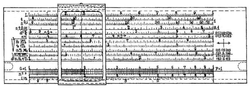
The drawing given on the patent for this slide rule (U. S. Patent 1,168,059) accurately represents how the System Cuntz slide rules actually manufactured and sold appeared, so, rather than attempting to describe the indescribable, here is that image:
which I have slightly retouched by removing the lines by which parts of the slide rule were labelled with letters to which the patent description referred.
Note also that on the right there were numbers for the purpose of indicating which of the two R scales or the three Q scales would be the right one on which to find the square or cube root of a number on the D scale, depending on the location of its decimal point. Some Pickett slide rules attempted to do something similar.
Duplex slide rules, even excluding those made for special purposes, offered such a wealth of possibilities that usually their only names were the trademarks of the individual maufacturer. The modern duplex slide rule was invented in 1890 by William Cox for the Keuffel and Esser company in the United States.
Duplex slide rules had many different assortments of scales. Some might only have the main set of three log-log scales, LL1, LL2, and LL3, and others would have four log-log scales in both sets of scales. But at each level of complexity, each manufacturer had its own arrangement of scales; this was particularly distinctive at the highest end of the line, where such flagship slide rules as the Pickett N4-ES, the Keuffel and Esser Deci-Lon, the Faber Castell Novo-Duplex 2/83, the Aristo HyperLog 0972, and the Post (Hemmi) Versalog each displayed radical differences in design philosophy.
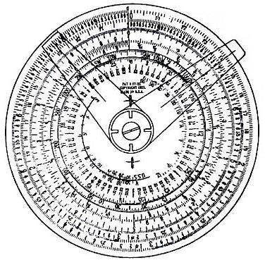
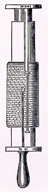
It is possible to move one logarithmic scale relative to another by using a rotating disk as well as a slider. The very first circular slide rules designed, almost immediately after the invention of the ordinary slide rule, instead used a single circular scale, with a pair of cursors whose relative position could be fixed. The Gilson Binary slide rule was a 20th-century slide rule designed on that principle, and it even had a log-log scale.
An image, from an old catalog, of a slide rule of this type (a smaller slide rule made by the makers of the Gilson Binary slide rule) is shown at right. It works on the principle that if one moves the cursor which is in contact with the surface of the disk, the upper cursor will go with it; this is achieved by making the pivot holding the spring holding the two cursors to the disk free to easily rotate.
Most recent circular slide rules did have a rotating disk and a single cursor instead, however. Each of these two forms of slide rule have their own vocal advocates. The advantages and disadvantages of each form of slide rule are, however, relatively obvious:
| Straight Slide Rule | Circular Slide Rule | |
| Size | In one direction, it must be as long as its scales, but in the other it can be quite narrow, depending on how many scales it has; the number of scales it can have is unlimited. | It can have scales over three times as long as its largest dimension, but it must be the same size in two directions. The more scales that are added to such a rule, the shorter they have to be compared to the rule's longest scale. |
| Ease of Use | All the numbers on every part of the rule are upright when in use. | One never has to worry about choosing the wrong index for a calculation so that the result goes off the end of the scale. |
Thus, from this table, the actual history of the slide rule is not surprising; the overwhelming majority of slide rules used for serious work during the heyday of the slide rule were straight slide rules, but special-purpose slide rules designed for use by people who would otherwise not use a slide rule were often circular, and the last slide rules still being manufactured after the pocket calculator are circular slide rules as well.
That is because the advantages of the circular slide rule applied to people new to slide rules and to slide rules with a limited number of scales, while the advantages of the straight slide rule were relevant to people who were trying to calculate rapidly and to slide rules with a large number of scales.
Some other differences between straight and circular slide rules vary with the type of circular slide rule being considered:
| Straight Slide Rule | Conventional Circular Slide Rule | Binary Circular Slide Rule | Clear Plastic Overlay Circular Slide Rule | |
| Scales in Contact | Either two pairs of scales, on a one-sided rule, or four pairs of scales, on a two-sided rule, slide against each other. | Either one pair of scales, on a one-sided rule, or two pairs of scales, on a two-sided rule, slide against each other. | Because the separation between the two cursors can be taken from any scale, and applied to any other, this slide rule acts as if any scale on the rule is sliding against any other scale. | If one set of scales is printed on a clear plastic overlay, instead of on a rotating disk within the rule itself, the number of scales that can be in contact with a scale on the body of the rule is arbitrary. |
| Parallax | All scales are in the same plane, and the cursor line can be printed on the back of the cursor window. | All scales are in the same plane, and the cursor line can be printed on the back of the cursor window. | The cursor lines can be printed on the back of both cursors, but the thickness of the first cursor separates the second cursor from the scales. | The second set of scales can be printed on the back of the plastic overlay, but its thickness separates the cursor from the scales. |
| Required Motions | Index to operand; cursor to other operand if scales involved do not touch. | Index to operand; cursor to other operand if scales involved do not touch. | First cursor to index; second cursor to operand; both cursors together so that first cursor is on second operand. | Index to operand; cursor to other operand if scales involved do not touch. |
Incidentally, one could put a cursor line aligned with the indexes of the scales on a plastic overlay slide rule to create a slide rule that can be used as a binary circular slide rule for calculations involving sets of scales other than those which are paired. Files in PDF format for making such a slide rule yourself on a laser printer are available here.
Also, a few years after they invented the duplex slide rule, Keuffel and Esser brought out a slide rule which used the braces holding the two pieces body of the slide rule in a duplex slide rule to also hold a middle portion of the body, so that the slider could consist of two sliders joined by a flat plate, so that instead of four pairs of scales, eight pairs of scales were in contact on the rule. This slide rule, the Universal, is now extremely rare and expensive. The principle does not seem to have been used again, although it would have been useful to allow specialized scales to coexist with the full complement of scales on a conventional duplex log-log slide rule.
The precision of calculations on a slide rule is, of course, quite limited. From time to time, various measures have been attempted to ameliorate this problem.
A straight slide rule can have a long scale split into several pieces in order to fit its length, leaving the user to either estimate the result or count scales to choose the correct answer. Hemmi made two slide rules of this type, the Hemmi 200 and the Hemmi 201.
The Hemmi 201 split the scale into four parts, and, in addition, it was 20 inches long instead of 10 inches long. The scales were:
L2,4 L1,3 A2,4 A1,3 | C4 C3 C2 C1 | D1 D2 D3 D4
K4 K3 K2 K1 | CF4 CF3 CF2 CF1 | DF1 DF2 DF3 DF4
Thus, it had L, A, C, D, K, CF, and DF scales, each split into four parts. Since the A scale is the same scale repeated twice, only two parts were needed, and thus those two pieces were called A1,3 and A2,4 to show that the first part was also the third part, and so on. Two parts of the L scale were also provided to make it easier to read the scales and label them.
The Hemmi 200 was only 16 inches long, but split the scale into six parts, making it somewhat longer, at 96 inches. The scales it provided were:
D6 D5 D4 | C6 C5 C4 C3 C2 C1 | D3 D2 D1
DF6 DF5 DF4 | CF6 CF5 CF4 CF3 CF2 CF1 | DF3 DF2 DF1
limiting it to just multiplication and division.
A humbler example from Britain was the Unique Ten-Twenty, a ten-inch slide rule with scales split into two parts.
A circular slide rule can have a long spiral scale placed on it.
The quest for a slide rule with a very long scale has, however, led to the design of a third type of slide rule, the cylindrical slide rule.
Three basic types of cylindrical slide rules are well-known, and are listed under the names of their most famous representatives.
In this type of slide rule, there is a cylinder which contains a long scale split into several segments, each segment fitting within the height of the cylinder, and the segments being uniformly distributed about its circumference.
This cylinder slides within a cage in which the bars have the segments of a corresponding scale on them.
Thus, the cylinder is rotated to place the required portions of the two long scales in contact, and then slid to bring the appropriate numbers in contact.
Since each bar has two sides, and the bars will generally be thicker than the minimum possible distance between scales, this design lends itself to a more complex type of rule with multiple scales, similar to a conventional slide rule; also, its manner of operation is very similar to that of an ordinary slide rule.
An old drawing of this slide rule is shown below:
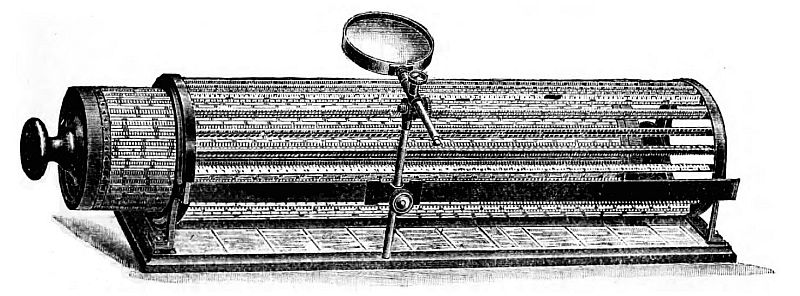
In addition to Edwin Thacher's invention of 1881, in which the inner cylinder and the cage both carried overlapping double-length segments of the divided scale for convenience in avoiding off-scale results, the Swiss company Loga produced a slide rule based on this principle which continued to be manufactured quite some time after Thacher's instrument ceased to be produced; it was patented in 1894, and was different in that the cage only had a single copy of each part of the scale, and was half the length of the cylinder, and it was the cage, rather than the double-length inner cylinder, was the component that slid, helping to make the instrument more compact. In addition, because the cage was placed on a cylinder of transparent plastic, the bars were much narrower, so there were 50 of them instead of 20, but the top side only of the bar was used, so the logarithmic scale was split into 50 parts instead of 40.
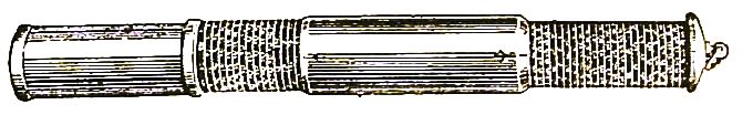
An earlier design belonging to this general group was the first known cylindrical slide rule, invented by the same Colonel Amédée Mannheim who revised the basic slide rule layout.
This slide rule consists of a body with a helical scale, within which a sleeve with a similar helical scale could both slide and rotate. An outer sleeve then slid and rotated on the helical scale on the body, being narrower at the other end so as to approach closely to the sleeve with the other helical scale. Marks at the two ends of the outer sleeve constituted the cursor of the slide rule; thus, instead of placing the two helical scales in coincidence, points on the two scales separated by the distance between the two cursor marks were treated as corresponding.
Below is an old drawing of this cylindrical slide rule:
The Otis King cylindrical slide rule was perhaps the most popular and inexpensive cylindrical slide rule made.
A special-purpose cylindrical slide rule made for use in sight reduction for celestial navigation, the Bygrave position-line slide rule, was based on the same general principle, although it was constructed differently, so that it looked more like the Fuller slide rule, which will be described next.
As I may have stimulated your curiosity by even mentioning this device, I will also recount an explanation of how it worked that I once gave, in a later section of this page.
An old schematic drawing of this type of slide rule appears on the right.
This slide rule, in its basic form, operated somewhat like a binary circular slide rule; a single scale, helical like those on the cylindrical slide rule of the Otis King type, was positioned between two cursors, then moved to bring one number to one cursor so that the result could be read at the other cursor.
The body of the rule bore the stationary cursor, which had two indicating points, separated by the length of the scale. A cylindrical sleeve, normally bearing tables and formulas rather than scales, had the second cursor, a single point, attached to it, and the scale itself moved on an outer cylindrical sleeve.
A later model then had indicating marks placed on the sleeve with the original scale, such that when these marks were placed against a scale on the sleeve attached to the second cursor, the corresponding point on the main scale would be at the second cursor. That sleeve had room for two additional scales, and in addition the L scale could fit in a single circuit of the cylinder, given a suitable number of turns to the helical scale.
Although complicated, it did have the advantage of making the most use of each moving part, and was perhaps the best-known cylindirical slide rule.
This special-purpose cylindrical slide rule was so designed that in three calculation steps on the rule, with some addition done by hand, it assists in what is termed sight reduction, the conversion of sextant observations for use in celestial navigation.
As noted above, although it was about the same size as the Fuller cylindrical slide rule, it actually worked according to the basic principle of the Otis King cylindrical slide rule instead. During its lifetime, there were three different basic versions of the device, illustrated at left.
The first version placed the two pointers inside of a window in the collar which contained the instructions for use of the device. This meant that the separation between the two pointers was limited, and therefore the two cylinders with spiral scales were also limited in height.
The second version solved that problem by placing the two pointers on top of the collar with the instructions. But it created a new problem: because now the lower pointer was on top of the collar with the instructions, an equivalent space on the bottom of outer one of the two cylinders with spiral scales was wasted.
The third version solved that problem as well, by bringing back a window, but this time only for the lower pointer.
The two scales are a T scale on the main cylinder (apparently, despite that scale being everywhere described as a scale of tangents, those who have examined actual specimens of the device have noted that it is, in fact, marked as a scale of cotangents) and an S scale, but labelled so as to show cosines rather than sines, and which runs in the reverse direction, on the outer cylinder (which I shall therefore call the CSI scale).
The three steps in its use are as follows:
Given the declination (or latitude in the sky) and the hour angle (or longitude in the sky: quite literally, as this is produced by applying the sidereal time to the right ascension of the object sighted), an intermediate value YLOWER is calculated from the expression
YLOWER = ATAN( TAN( DECLIN ) / COS( HRANG ) )
by (in straight rule terms) placing the index of the T scale over DECLIN on the CSI scale, and then reading YLOWER on the T scale over HRANG on the CSI scale.
The modified intermediate value YUPPER is then 90 degrees minus your current latitude, and either plus YLOWER if the declination and latitude are both in the same (north or south) hemisphere, or minus YLOWER if they are in opposite hemispheres.
One then calculates the azimuth to the star from the equation
AZIM = ATAN( COS( YLOWER ) * TAN( HRANG ) / COS( YUPPER ) )
by placing HRANG on the T scale over YLOWER on the CSI scale, and then reading AZIM on the T scale over YUPPER on the CSI scale.
Finally, the altitude (which is normally what one obtains from a sextant in the first place, but the difference between the altitude calculated with this instrument from the estimated position of your ship and the actual altitude seen with your sextant is what you plot on a chart in celestial navigation) is calculated by
ALT = ATAN( COS( AZIM ) * TAN( YUPPER ) )
which is done by placing YUPPER on the T scale over AZIM on the CSI scale, and then reading AZIM on the T scale over the index of the CSI scale.
A derivative of the Fuller slide rule was used for multiplying complex numbers.
When expressed in polar coordinates, multiplying two complex numbers becomes multiplying their radii, and adding their angles; using the logarithms of their radii, this reduces to adding two independent numbers, which can be done mechanically.
Thus, one can take the following area on the complex plane:
and map it to a rectangular area, which could serve as the slider of a slide rule, with a corresponding area on its base:
The slide rule actually built used a single scale of this type, rather than two scales, one still and one moving, but it used all four quadrants of the complex plane, wrapping them around a cylinder. It was made by W. F. Stanley and Company in 1961, having been designed by one D. J. Whythe to fill a request from the BBC, and resembled the Fuller cylindrical slide rule in general design.
One could make the angular coordinate correspond to the radius, and the radius correspond to the angle, around a circular slide rule for complex multiplication.
Since this was written, I've learned from a page on the web site of the International Slide Rule Museum that the Faber-Castell 989 Complex Slide Rule Calculator also used a scale of this type; it was stationary on a flat surface, with a cursor having a pivoting arm to allow calculation.
There's considerably more information about complex number slide rules on this page.
Logarithms were originally invented by John Napier in 1614. In 1620, Edmund Gunter first noted that a logarithmic scale could be used in combination with a compass for measuring out distances along it to perform multiplication. And then the slide rule itself was invented in 1632 by William Oughtred. The modern form of the slide rule, in which two pairs of scales slide against each other, so that the rule is composed of a slider and a stock, was at one time credited to Seth Partridge in 1657, but it is now known he was describing an earlier invention, believed to be that of Robert Bissaker in 1654.
Unlike logarithm tables, which remained an important aid to calculation ever since their invention and until the emergence of the pocket calculator. the slide rule appears to have languished in relative obscurity from Oughtred to Mannheim. Although a few scientists and engineers did make use of the slide rule, its chief popularity in the first part of its existence appears to have been as a tool for calculating taxes on barrels of alcoholic beverages in Britain.
Before Mannheim, the typical scale layout on a slide rule would be what we would call in modern terms:
A/B B/D
Thus, the A and B scales were used for multiplication, and the bottom pair of scales could be used for multiplying one number by the square of another number. This arrangement avoided the need for a cursor, but limited the accuracy of a 10-inch slide rule to that of a 5-inch slide rule with C and D scales.
It takes some effort to learn how to multiply with the C and D scales, and making a cursor whose hairline remains accurately perpendicular to the scales requires some effort. But all these things were possible long before 1859.
The cursor, also known as a runner or index, although perhaps invented either by Robert Bissaker or Isaac Newton, became known around 1778, in a slide rule designed by John Robertson, and the use of C and D scales for multiplication had been introduced even earlier, by a British excise examiner named J. Vero (or Verie).
Thus, it must be concluded that before Mannheim, there was not enough potential demand for the slide rule for this type of innovation to succeed. Prior to this, the popularity of the slide rule had been growing in some countries, while in other countries in Europe, it still remained almost unknown, during the first half of the nineteenth century; it was after Mannheim that the slide rule could no longer be ignored: that generations of schoolchildren might be trained in the use of the slide rule changed from impossible to inevitable.
It was not until 1886, however, that the firm of Dennert and Pape, later responsible for the quality plastic slide rules that sold under the Aristo brand name, invented the slide rule construction involving putting the scales on a thin layer of celluloid, then attached to a wooden base, greatly improving the legibility of slide rules.
The first slide rule with a scale the length of which was a multiple of the length of the rule itself, to permit more precise calculations to be performed, was proposed by William Nicholson in 1787.