The elaborate scheme of memory addressing outlined on the preceding page for a computer which accessed aligned 36-bit, 48-bit, and 60-bit floating-point numbers within a memory composed of 720-bit wide units clearly would require a considerable amount of additional hardware, and would likely cause delays in address calculation. Is it possible to achieve the desired level of flexibility, while making some compromises elsewhere, to obtain an architecture nearly as simple as a conventional computer?
Incidentally, the basic principle used here to eliminate the need for a divide-by-three operation in addressing has been used in real life, I have discovered. U.S. Patent 5,860,076 (inventors: Spencer H. Greene and Andrew D. Daniel, assignee Alliance Semiconductor) deals with placing 32-bit numbers in a memory that is 48 bits wide (apparently with video cards as the major intended application) by placing one in each location, and then placing an additional group of 32-bit numbers in the remaining 16 bits of two consecutive locations. With the principle as I employ it here, numbers are not split between memory locations, because I propose the use of a wider memory bus.
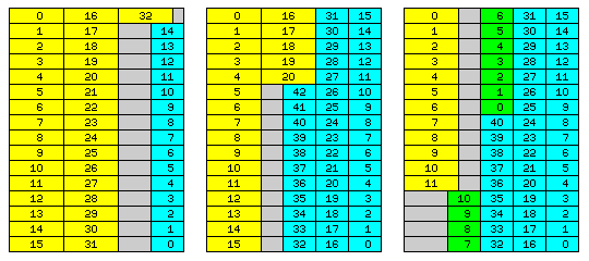
One possibility is illustrated by the diagram above.
The unit common to floating-point numbers that are 36, 48, and 60 bits in width is 12 bits.
If one uses a 6-bit character as the basis, and uses pure power-of-two addressing, as on the IBM 360, then 6-bit, 12-bit, 24-bit, and 48-bit items can be handled easily.
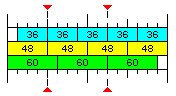
Let us consider a memory which is composed of units 192 bits in width, which would be sixteen 12-bit fundamental units.
This is enough space for exactly four 48-bit floating-point numbers.
As well, sixteen is one greater than fifteen, so one could, as in the diagram above, establish standardized positions for 36-bit and 60-bit floating-point numbers, and treat those as their natural "aligned" positions, thus ensuring that a fetch of a 36-bit float or a 60-bit float would never require two separate 192-bit memory lines to be fetched, as that boundary would never be crossed. There would be a wastage of one fifteenth of memory, however, in an area exclusively used for floats of either of those awkward sizes.
However, 192 bits could be shared, without wastage, either by one 48-bit float and four 36-bit floats, or by two 60-bit floats and two 36-bit floats.
Note that the memory could be constructed from standard parts, even if ECC is desired.
For SECDED capability, eight bits could be associated with 96 bits of memory. So, 16 ECC bits, and 192 data bits, could be provided by using two 72-bit, and one 64-bit, memory stick of equal capacity in a matched set of three.
How could the 36-bit floats and the 60-bit floats be addressed in a simple way?
Clearly, quantities that are 6, 12, 24, 48, 96 or 192 bits in width would be addressed in the same normal direct fashion as on an IBM 360, as pure linear addressing would directly provide for observing alignment restrictions by setting the appropriate number of the least significant bits of the address to zero.
Since 12-bit quantities can be addressed, a 36-bit float can be conventionally addressed simply by using its starting address, and the same applies to a 60-bit float. This, simply with possible restrictions on position within the 192-bit memory word, suffices for single variables. It's really only when indexing is used for arrays of numbers of this length that the awkwardness of an irregular distribution of starting positions is something that needs to be avoided, and this is why the feature being proposed here to allow convenient addressing of such items as being in evenly-spaced successive positions is shown as something which does not need to be used, and if it is used, is applied in a flexible manner.
It is envisaged that addressing of 36-bit and 60-bit quantities would be simplified as follows:
An area, consisting of a number of 192-bit memory lines that is a power of two, would be set aside to contain numbers of these types.
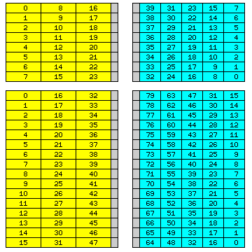
Let us take, as an example, 256 such memory lines.
In the case of 60-bit floating-point numbers, then, it would contain 768 such numbers. The numbers with relative addresses from 0 to 255 would all be in the first five 12-bit fundamental units of each 192-bit memory line, and they would be in successive memory lines. Those with relative addresses from 256 to 511 would all be in the second group of five 12-bit fundamental units, and, again, they would be in successive memory lines. And those with addresses from 512 to 767 would be in the third group of five 12-bit fundamental units.
In the case of 36-bit floating-point numbers, there would be 1280 such numbers. This time, the numbers with relative addresses from 0 to 255 would all be in the last three 12-bit fundamental units of each 192-bit memory line, but again in successive memory lines. Originally, it was envisaged to have them go forwards, not backwards, but inverting the eight bits that indicate which of 256 items is chosen would permit more options in combining arrays of 60-bit and 36-bit numbers in a memory area. Those with relative addresses from 256 to 511 would be in the second-last group of three 12-bit fundamental units of each 192-bit memory line, and so on.
Thus, the diagram below illustrates how this principle would work when 8 or 16 lines of 192 bits, rather than 256 of them, were so reserved:
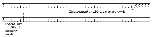
Thus, the last few bits of a displacement are simply shifted left to form a displacement in units of 192 bits, while the first few are used to select which of the floating-point numbers of the required length within a given 192-bit memory line is desired. Thus, the circuitry required for converting addresses is simple, not requiring multiplications or divisions, even by fixed quantities. And, taking 60-bit quantities from the left, and 36-bit quantities from the right, allows mising them in the correct proportions to achieve full efficiency.
To further improve the ability to handle arrays of odd lengths, in the case of 36-bit quantities, the bits used for a displacement in units of 192 bits are also inverted. This would not work well in all cases, however.
It is envisaged that the first few bits of the contents of a base register might be used to indicate the number of bits in displacements for 60-bit or 36-bit floating-point items that are used to address a 192-bit memory line.
The diagram below shows how this might work in this example, using 48-bit base registers:
The first bit of a 48-bit base register would indicate if this feature was used in the area of memory which it points to.
If not, then the base register would contain a normal address in 6-bit characters. In order to avoid the expected alignment of addresses in instructions using base-relative addressing being disturbed, that address would need to be on a 192-bit memory word boundary, and so the last five bits would normally be zero.
If this feature is used, as indicated by the first bit being 1, then the next six bits would be required to indicate the size of the extent to be used, since extents might be small, for efficient packing of small arrays, or they might be quite large, for computing on large, sparse arrays which would not be brought into the cache. The address portion of the base register contents would be that of a 192-bit memory word, not a character address. A penalty is paid, therefore, in the form of a reduction in the size of available virtual memory, but it is only cut in half when this feature is used - or, alternatively, this feature can only be used in the first half of a virtual memory of 140,737,488,355,328 6-bit characters or 4,398,046,511,104 192-bit memory words.
On the other hand, while 24 bits is a reasonable size for many integer calculations, it will be too short for addresses. Making the base registers 48 bits wide would be reasonable, given that microprocessors with 64-bit operating modes still have 40-bit or 48-bit physical addresses.
While 60-bit floating-point numbers can share space easily with 36-bit floating-point numbers in one particular ratio, the addressing scheme shown could equally well be used with 64-bit floating-point numbers - avoiding having to divide the value in the index register by three to get a physical address, and avoiding wasting 12 bits out of every 192. That has the additional advantage of allowing 32-bit, 16-bit, and 8-bit datatypes to be addressed within a 64-bit word.
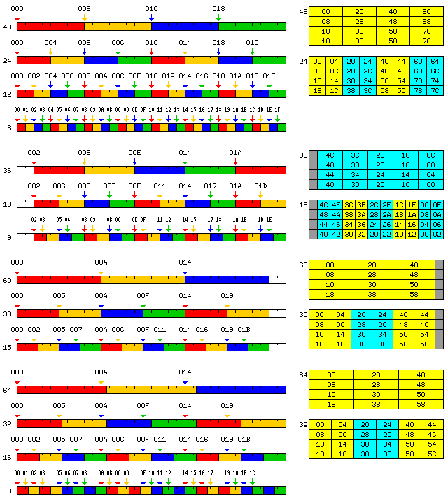
This diagram will illustrate more clearly how displacements are processed:
For purposes of this diagram, a "displacement" means whatever is added to the base register contents to form an effective address: thus, in the case of indexed addressing, it means the sum of the contents of the specified index register and the address or displacement field of the instruction.
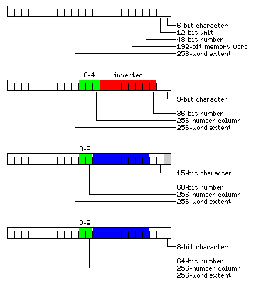
First, a normal displacement is illustrated. This displacement is shown as a character displacement, in units of 6-bit characters. Thus, all but the last bit is a displacement in units of the 12-bit common unit of memory, all but the last three bits is a displacement in units of the 48-bit floating-point number, as indicated on the diagram. Four such numbers make up the 192-bit memory words which are physically addressed externally, so that the memory will supply a 192-bit data bus.
The second portion of the illustration shows what is done where a displacement is used to find a 36-bit floating-point number.
For illustration, the case is used where 256 memory words are bundled together to contain up to 1,280 36-bit floating-point numbers.
The group of bits shown in red are inverted, so that 192-bit memory words are used starting from the end of the 256-memory-word extent to improve the efficiency of coexistence with 60-bit floating-point numbers. Then, they end up being shifted left by three places to form part of a conventional displacement, which allows a 192-bit memory word to be addressed normally.
Thus, the three bits marked in green are taken out, and used to pick which of the five 36-bit numbers in a 192-bit memory word is to be used, according to the conventional aligned positions shown in the first diagram on this page.
The third portion of the diagram shows the case of 60-bit floating-point numbers. Here, the portion of the address that is shifted left to indicate which 192-bit memory word is to be used is shown in blue, as it is not inverted. The two bits to be removed show which of three 60-bit floating-point numbers in a 192-bit memory word are to be used.
The final portion of the diagram shows how 8-bit characters would be addressed as parts of a 64-bit object; since 64 bits are exactly one-third of a 192-bit memory word, the only difference being that there are no longer 12 left-over bits as with 60-bit floating-point numbers, those 64-bit objects are addressed in the same fashion as 60-bit floating-point numbers, although slightly different portions of the 192-bit memory word are used.
At this point, it should be apparent what is being done. In order to make use of the flexibility provided by a 48-bit word to handle items which are 8 bits, or 36 bits, or 60 bits in width, without ever having to divide an address by three or by five in order to access its location in a memory organized around the 48-bit word, the day of reckoning, when the boundary of a 192-bit memory unit, containing three 60-bit floats, or five 36-bit floats, or twenty-four 8-bit bytes, in each case, a number that is not a power of two, is crossed is postponed by fetching successive items from different 192-bit memory units, within a block that contains a power-of-two number of them. The block size is variable, so that no matter how large an array might be, as long as it can fit within the available virtual memory space, the day of reckoning, when this incompatibility between the width of an item and that of the computer's physical memory has to be confronted, can always be postponed long enough so that it never actually happens.
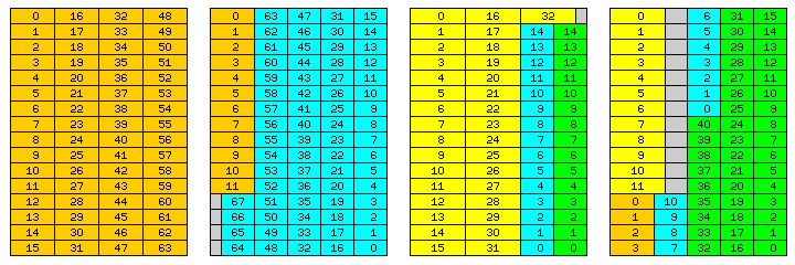
The reason that the sum of the address field of the instruction and the contents of the index register, and not the contents of the index register alone, are processed as noted above is illustrated in the third part of the following diagram:
This illustrates how, in an extent consisting of sixteen memory words of 192 bits, various combinations of arrays of 60-bit double-precision floating-point numbers and 36-bit single-precision floating-point numbers could be combined with greater or less efficiency.
In the first diagram, an array of 33 double-precision numbers shares space with one of 15 single-precision numbers. In the second diagram, an array of 21 double-precision numbers shares space with one of 43 single-precision numbers.
In the third one, an array of 12 double-precision numbers shares space with 52 single-precision numbers; those single-precision numbers belong to one array of 41 single-precision numbers, and another array of 11 single-precision numbers, shown in a different shade of green. It is precisely because the sum of the displacement within the instruction and the index register contents is what undergoes processing that a position within the sequence of locations that a single array of 52 single-precision numbers would occupy could be used as the starting point for an array of 11 single-precision numbers, with the sequence of their positions in storage continuing to follow the same pattern.
Note that since there are an odd number of 64-bit floats in 192 bits, however, a 128-bit object could not be well-aligned. Presumably, extended precision floats would be 96 bits long.
Thus, it is envisaged that a computer featuring the capabilities discussed here would support the following floating-point types:
with 64-bit floats addressed conventionally as if they were 60-bit floats packed to the left of a 192-bit memory line, and 32-bit floats addressed conventionally as if they were 30-bit floats (with addresses on 6-bit boundaries instead of 12-bit boundaries) packed to the left of a 192-bit memory line.
Note also that while 9-bit characters can be easily addressed as portions of a 36-bit word, 8-bit characters, while they fit in a 48-bit word, are six to a word, which is not a power of two. Thus, instead, they would be most easily addressed as portions of a 64-bit word, where 64-bit words would be addressed in much the same way as 60-bit floating-point numbers, three to a 192-bit memory word.
A 10-bit unit of storage also needs to be considered. Efficient packing of decimal digits using Chen-Ho encoding leads to three decimal digits being stored in a ten-bit unit. Since six such units, not a power of two, would fit in a 60-bit unit, simply addressing them from left to right within a 60-bit unit would fail to avoid the need for divide-by-three circuitry in addressing.
This can be avoided, however, by allocating 10-bit units independently, or addressing two of them from left to right within 20-bit units that are allocated independently, using the same basic scheme as that used for allocating 60-bit floating-point numbers.
Thus, a 192-bit memory line would contain either three 60-bit floating-point numbers or nine 20-bit storage units, and a group of eight memory lines, for example, would become nine successive columns of eight 20-bit memory units, with the lower three bits of the displacement selecting which unit in a column was addressed, and the next higher four bits selecting which column was referenced.
However, nine 20-bit storage units use only 180 out of 192 bits, and it is possible to do better with 10-bit storage units - nineteen of them, allocated independently, use 190 out of 192 bits.
And therefore the available addressing modes for each operand length would be:
                                                     6  8  9 10 12 15 16 18 24 30 32 36 48 60 64 96
                                                   -------------------------------------------------
Conventional                                       | X|  |  |  | X|  |  | X| X| X|  | X| X| X|  | X|
                                                   -------------------------------------------------
  As if conventionally addressed, but with         |  |  |  | X|  |  |  |  |  |  | X|  |  |  | X|  |
  an offset from actual position                (1)|  |  |  | 6|  |  |  |  |  |  |30|  |  |  |60|  |
                                                   -------------------------------------------------
  As if conventionally addressed, but offset       |  | X| X|  |  | X| X|  |  |  |  |  |  |  |  |  |
  from the starting point of an aligned item    (2)|  |32|18|  |  |30|32|  |  |  |  |  |  |  |  |  |
                                                (3)|  |30|  |  |  |  |30|  |  |  |  |  |  |  |  |  |
                                                (1)|  | 6| 6|  |  |12|12|  |  |  |  |  |  |  |  |  |
                                                   -------------------------------------------------
Forwards by column from the left                   |  |  |  | X|  |  |  |  |  |  |  |  | X| X| X|  |
                                                   -------------------------------------------------
  From the left within a 60- or 64- bit unit       |  | X|  |  | X| X| X|  |  | X| X|  |  |  |  |  |
  allocated forwards by column from the left       |  |  |  |  |  |  |  |  |  |  |  |  |  |  |  |  |
                                                   -------------------------------------------------
Backwards by column from the right                 |  |  |  |  |  |  |  |  |  |  |  | X|  |  |  |  |
                                                   -------------------------------------------------
  From the left within a 36-bit unit               |  |  | X|  |  |  |  | X|  |  |  |  |  |  |  |  |
  allocated backwards by column from the right     |  |  |  |  |  |  |  |  |  |  |  |  |  |  |  |  |
                                                   -------------------------------------------------
(1) As if it was of this length.
(2) Within an aligned item of this length.
(3) As if the aligned item had this length.
Instruction mnemonics would normally indicate which of the three main addressing modes was used, with the ones with an indented description being given the same indication as the main addressing mode immediately preceding them.
When an opcode specifies addressing that is by column, the block size is determined by the contents of the base register used. If the first bit contained in the base register is zero, then the instruction operates as if conventional addressing were specified instead. Thus, when the contents of a base register indicate addressing by column, that can be overriden by using an instruction that specifies conventional addressing; when, instead, the contents of the base register indicate conventional addressing, since no block size is provided, this cannot be overriden, and all instructions perform conventional addressing.
The following illustration shows how some of these addressing modes would work in practice, with conventional addressing for operands of different lengths shown on the left, and addressing by column for operands of some of the same lengths shown on the right, with extents of length 4 used in the examples:
Another issue is that while the addressing mechanism described so far lets storage be allocated for data based on the pure 6, 12, 24 and 48-bit series in the conventional manner, and a mix of equal numbers of 60-bit and 36-bit floating point numbers be allocated with full efficiency, if 60-bit and 36-bit data is required in another ratio, some wasted storage is inevitable.
This excludes another possibility for full efficiency noted at the beginning: 192 bits can also contain one 48-bit word and four 36-bit words. Thus, the option should also exist to address 48-bit words as if they were 60-bit words.
The first of four parts of the diagram below shows how this feature would work, and the second part shows an example of how if might be normally used in a simple fashion. The fourth part of the diagram below shows how this feature could be used to increase the maximum effective packing of easily-addressable data in memory:
In the third part, we see that while having an array of 33 double-precision numbers in an extent of 16 memory words limits the maximum size of an array of single-precision numbers that can share such an extent to 15 single-precision numbers, the space originally shown as unused could still be used for a second array of 15 single-precision numbers. In the fourth part, again using the principle which the third part of the diagram illustrates that an array of numbers can start at a position other than the beginning of the sequence of location for numbers of that length within an extent, even if numbers of a different length intervene, a small array of four numbers with 48-bit precision, addressed using the scheme applied to numbers with 60-bit precision, is shown as being placed after the array of twelve double-precision numbers in what was previously depicted as unused space.
Thus, while the base register contents indicates how 36-bit words and related items, such as 9-bit characters, are to be addressed, and how 60-bit words and related items, such as 64-bit words and 8-bit bytes, are to be addressed, whether a given instruction addresses conventional 48-bit words or 6-bit characters on the one hand, or data items of a length which require special handling is indicated by the opcode of the instruction. Alternate opcodes for processing data items of conventional widths related to 48 bits by a power of two can be used to squeeze them in with 36-bit words by giving these 48-bit items the same special handling as 60-bit items.
48-bit words could be mixed with 36-bit words addressed by the usual mechanism, or, if the ratio does happen to be perfect, locality of reference could be improved by addressing 36-bit floating-point numbers conventionally; that is, addressing the four 36-bit floating-point numbers occupying the last 144 bits of a 192-bit memory word as if they were the four 48-bit floating-point numbers that would fill that memory word. This would again require an alternate set of opcodes, this time, one for performing operations on 36-bit floating-point numbers. (Since the perfect mixture of 60-bit and 36-bit items is two of each in 192 bits, another option for alternate opcodes to allow conventional addressing to work is also present; in this case, 36-bit words would be addressed as though they were 96 bits long instead of 48 bits long.)
Note that this envisages that level 2 cache would basically image external memory; level 1 cache, on the other hand, would cache groups of items taken from memory in their natural order, regardless of their length and the steps needed to pack them efficiently in memory.
Doubling the width of a memory word from 192 bits to 384 bits would provide an additional option for full efficiency, with four 60-bit floats followed by six 48-bit floats; doubling it again would turn the leftover 12 bits when either 36-bit or 60-bit floats are used exclusively into one usable 48-bit float.
Note, also, that this addressing principle could also be used to avoid the need for divide-by-five and divide-by-seven circuits in a more conventional computer with a 256-bit data bus to memory, where seven 36-bit floating-point numbers occupy 252 bits, with 4 bits left over, or five 51-bit floating-point numbers occupy 255 bits, with 1 bit left over.
Or one could stay with 48 bits for intermediate precision, but use 40 bits for single precision. It would seem hardly worthwhile to have two precisions so close together, though, even if 96 plus 160 makes 256, the same way as 120 plus 72 makes 192, for one particular ratio of numbers of each precision permitting full efficiency.
On the other hand, the choice of a 192-bit bus instead of the 720-bit bus described on the previous page does work better, because conventional addressing can work on a 6-bit character, which is smaller than both an 8-bit character and a 9-bit character, so that addresses don't need to be padded in most cases, and the portions of displacements which refer to a block of 192-bit memory words can be kept in a constant position.
Also note that since the scheme as outlined here is concerned with flexibility in mixing 36-bit and 60-bit numbers in a memory designed for 48-bit numbers, another option which would improve locality of reference, and which would have more closely resembled the scheme in the patent cited, was not considered; 36-bit quantities which come as five to a memory word, or 60-bit quantities, which come as three to a memory word, could have been addressed like this:
 0  1  2  3 16
 4  5  6  7 17
 8  9 10 11 18
12 13 14 15 19
in the case of 36-bit quantities, or like this:
 0  1  8
 2  3  9
 4  5 10
 6  7 11
in the case of 60-bit (or 64-bit) quantities.